I’ve just got a Mikrotik RouterBoard RB250G. While searching for useful information about its capabilities found very interesting article in the MikroTik Wiki: SwOS/Router-On-A-Stick
This article gave me the idea to use pfSense as a router and trunk a few VLANs.
Scenario
My aim is to reproduce the configuration from the above mentioned post with three VLANs, trunked on a single LAN interface (aka Parent interface) to the pfSense. To make it more usable, every VLAN will be on separate port on the switch (aka Access Port) and have its own instance of DHCP running on the pfSense. In this way, when a client connect to some of the ports he/she will automatically receive configuration contextual to VLAN on this port.
For the installation and basic configuration of pfSense on VMware take a look my previous post Install pfSense 2.0 RC1 on VMWare Workstation 7
The difference here is that the LAN virtual NIC is bridged to the second physical NIC of my workstation and from there directly connected to the RB250G switch.
We start with installed pfSense 2.0 RC1, configure WAN port bridged to my first physical NIC, and LAN port connected to my second physical NIC. For the sake of convenience and because of the problems that I faced initially with the communication on my second NIC, I decide to manage the router through the WAN interface, because its configuration will not change during testing. More on the topic VMware Workstation Virtual Machine and VLANs support, you can find at the bottom of this post.
There are two ways to configure VLANs in pfSense as long as I’m aware. One is through the console and the other is using the Web GUI. Here I will use the latter.
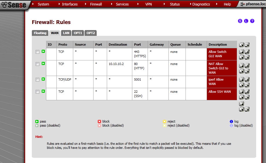
WAN Rules
First let’s configure Rules on the WAN port to allow access to the Web GUI.
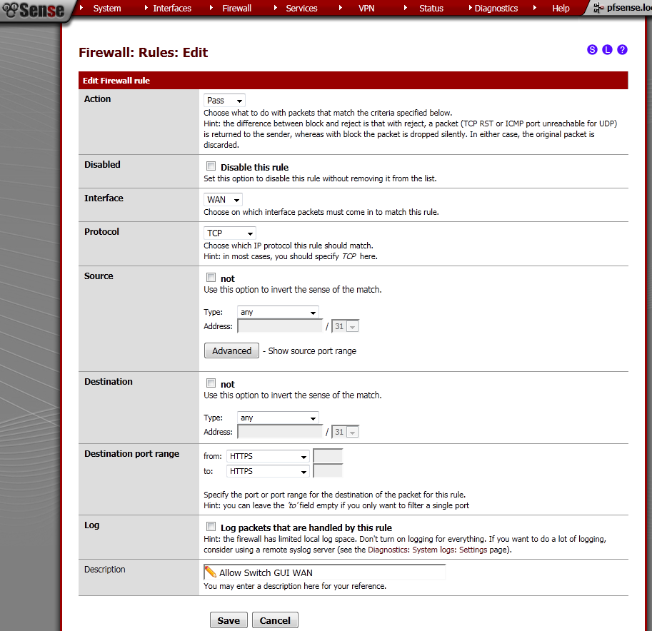
Got to Firewall > Rules, on the WAN leaf, add new rule.
The Interface is WAN, Protocol is TCP. Destination port range is HTTPS, enter and description.
This will allow access to the pfSense WebGUI on the WAN IP Address.
Creation of VLANs and Interfaces
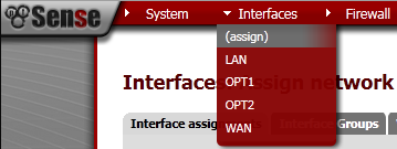
Go to Interfaces> (assign).
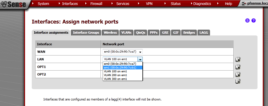
Make sure that you second Network port is not assigned to any Interface, if it is removed it. In my case this is em1. This machine has two interface em0 for the WAN, and em1 for the LAN.
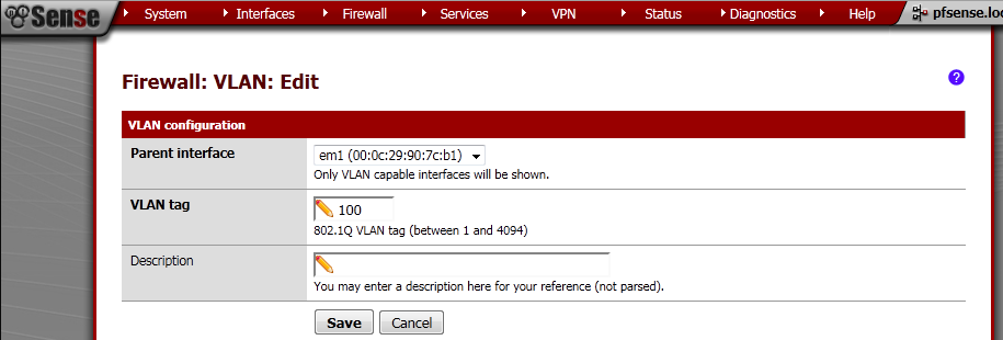
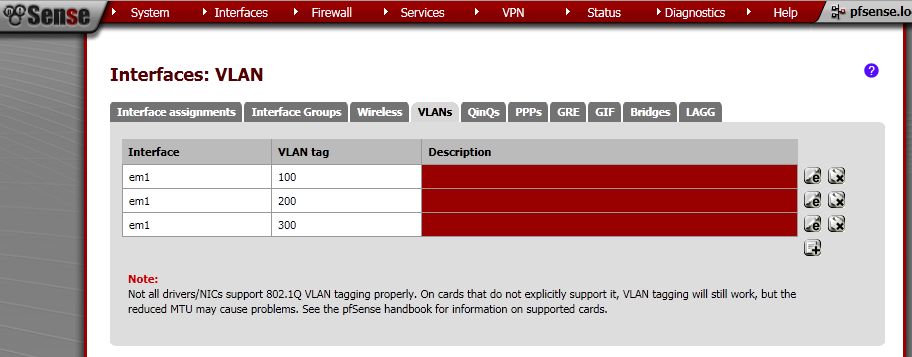
Go to the VLANs leaf, click on the add button.
On the new page make sure that Parent interface is em1. Enter VLAN tag number different from 1.
I’ve made three VLANs – 100, 200, 300.
Now we need to assign these as Interfaces, go to Interface assignments and then add them one by one, select the proper Network port which are the VLANs that we have just created, and do not assign em1 to any Interface directly.
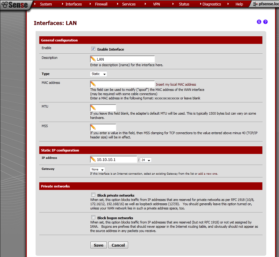
Now select LAN interface from the drop down menu under Interfaces. Tick Enable Interface, as type select Static. Under Static IP configuration, enter IP address and subnet mask.
In my case it is 10.10.10.1/24.
Repeat this procedure for all the VLAN interfaces. For reference these are the IP addresses that I have used:
LAN – 10.10.10.1/24
OPT1 – 10.10.9.1/24
OPT2 – 10.10.8.1/24
Interfaces Rules
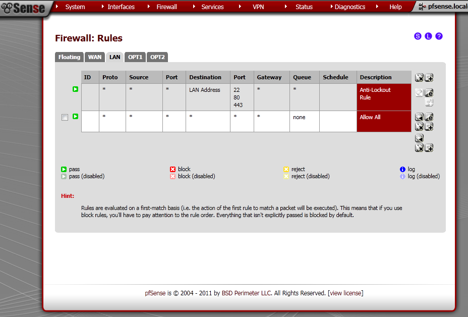
For the sake of simplicity every interface will be allowed communication to everywhere.
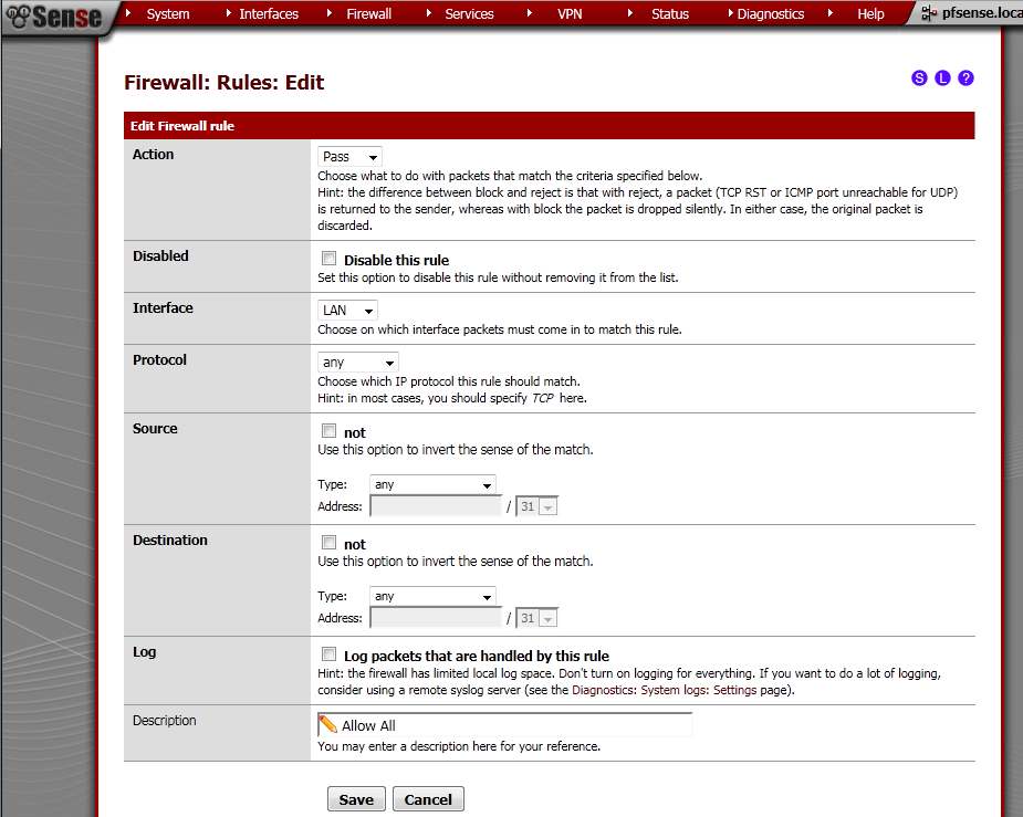
Go to Firewall > Rules, on the LAN leaf.
Add new Rule
Action is Pass, Interface is LAN, Protocol in Any, Source is Any, Destination is Any, enter some Description too.
Repeat this step on OPT1 and OPT2 leafs too.
DHCP Server Configuration
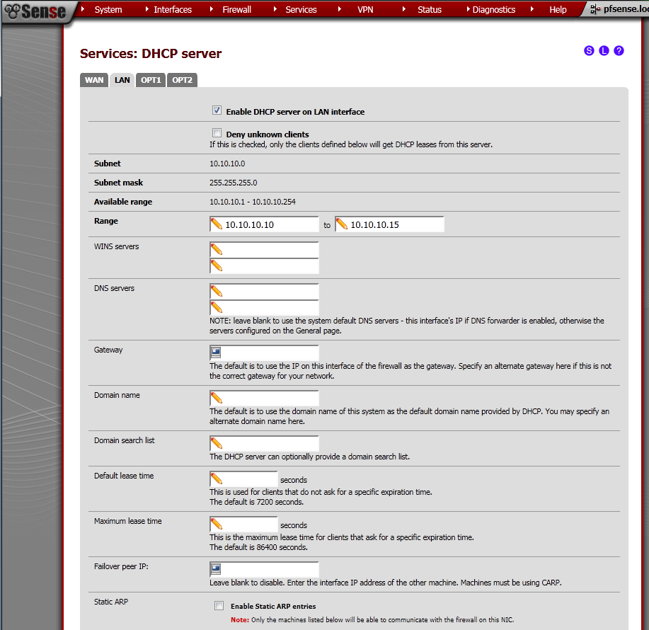
Go to Services > DHCP Server page.
On the LAN leaf, tick Enable DHCP server on LAN interface.
Enter Range from the subnet of the interface, in my case 10.10.10.10 – 10.10.10.15
Click the Save button.
Repeat the procedure for the OPT1 and OPT2 leafs. In my case the ranges were.
LAN – 10.10.10.10 – 10.10.10.15
OPT1 – 10.10.9.10 – 10.10.9.15
OPT2 – 10.10.8.10 – 10.10.8.15
Mikrotik RouterBoard RB250G Smart Gigabit Switch with five ports and SwOS v1.5
Before configuring VLANs on the switch, make sure that your firmware version is 1.2 or higher, by the time of writing this version 1.5 of the firmware is available. Otherwise you may run into problems that are related to applied functionality of the device.
Switch VLANs Configuration
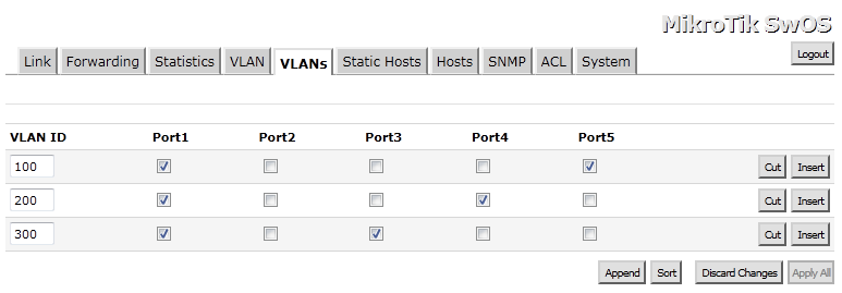
On the Switch, go to the VLANs leaf, add the same VLANs from the router. As for ports member always add Port1 and choose one of the other ports. This is the tricky part, my pfSense router is connected to Port1, which makes it Trunk port and must be a member of all VLANs.
In my example
Port 5 is member of VLAN 100
Port 4 is member of VLAN 200
Port 3 is member of VLAN 300
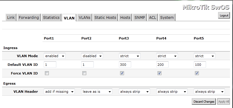
On the VLAN leaf.
For Port 1, our Trunk Port – VLAN Mode is Enabled, default VLAN ID is 1 and VLAN Header is Add If Missing.
For the other Access Ports the configuration is as follows: VLAN Mode is Strict, Default VLAN ID is configured by your design, from the VLANs configured on the router. You can leave Force VLAN ID unpicked, VLAN Header is Always Strip.
Testing
Now if you plug the test laptop to one of the Ports 3,4,5. And the NIC is configured to receive configuration from a DHCP server, you will get IP address from the subnet of the configured VLAN range. Because of the Allow All traffic rule you will have Internet, and access to host on the other VLANs.
Issues
Some issues that I faced along the way.
VMware Workstation Virtual Machine and VLANs support
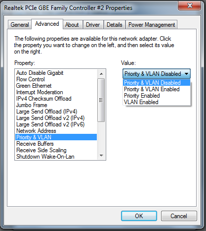
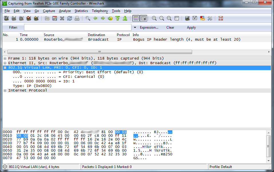
My idea was to configure quickly one VM with pfSense, and use the bridged interface for connection to the switch. Everything works fine up until I configured VLANs. Then suddenly the communication between the route and switch stops. After a little network sniffing what surprised me, was that the packets were not tagged with VLANs. After extensive googling on the topic, I did not found definitive reason for this strange behaviour. One part of the information was related to the physical NIC support of VLANs. The other portion of the topics were about the VMware VM and the type of the virtual NIC configured on the virtual machine. Unfortunately my EVGA X58 motherboard is equipped with two on-board Realtek NICS, but fortunately enough they support VLAN and event Priority. When I check the configuration of the bridged NIC Priority & VLAN were Enabled.
The troubleshooting took me long hours, but finally I’ve got a great idea. What if I turn off the Priority & VLAN support on the physical NIC? And indeed, packets start showing with the 802.1Q Tags. My suspicion is that the physical NIC strips off the VLAN tag, and this is the cause of the disruption in communication between my router and switch.
Mikrotik RouterBoard RB250G
If you ping the switch the pings are around 17-9 ms, which is huge taking in to account the device is directly connected.
For more information look here:
Pings TO the switch dropped, high ping…
References:
- To get a feeling of the switch Web GUI, take a look here, all interface pages are shown and all options are explained : http://wiki.mikrotik.com/wiki/SwOS
- This wiki article gave me some ideas for VLANs configuration: http://wiki.mikrotik.com/wiki/Manual:Interface/VLAN
- I like this thread in the forum, probably in future will try to separate Voice and Data in to separate VLANs as discussed: Topic: Setting UP VLAN in pfSense 2.0? http://forum.pfsense.org/index.php?topic=34739.0
- If you are seeking for a Smart Switch take a look at that thread: Smart Switch – Recommendations
MikroTik Forum useful links:
The Section about Mikrotik RouterBoard RB250G:
SwOS
Some interesting threads:



Hey Stefan, very interesting setup. Good job! We have almost the same setup on a Win7
SP1 host with pfSense RC3. But we face some problems when using full size ip frames. E.g. a ping from pfsense cmd line to the laptop works with ping -s 1468 10.0.5.101. But a ping -s 1469 10.0.5.101 will return to the host, but never reach pfSense guest. What is your experience? Thanks, Michael
I haven’t tested that, but probably soon I will have opportunity and will try it and write back.
I’m quite pleased with the infomratoin in this one. TY!
Hi Stefan.
Which Mikrotik router you suggest me to buy nowadays?
Thanks!